Nu har jag gjort en mackapär igen och jag tror att det är mitt kanske bästa verktygsbygge hittills. Det blev ytterligare en fräsvagga, fast lite mindre och lättare än modellen jag gjorde förra året. Främsta syftet var att göra gitarrhalsar, men har efter första provanvändningen insett att det även går att göra greppbrädor. Så, resultatet blev ett multifunktionellt verktyg som kan användas till mer än en sak!
Att göra halsar är bland de roligare momenten i ett gitarrbygge men det tar ganska lång tid. Så för att få upp produktionstakten började jag forska runt lite på nätet för inspiration. Och efter en tid så började jag att skissa lite i huvudet på idén. Som alla vet så fungerar teorin inte alltid i praktiken och det var verkligen en chansning att bygga ett verktyg där jag inte visste om det skulle fungera. Men resultatet överträffade mina förväntningar.
Med den här mackapären kan du i stort sett skapa vilken halsprofil som helst. Halsprofiler som C, D, U eller V men även mer avancerade progressiva, asymmetriska halsar. Vill man skapa greppbrädor som har olika radier från band 1 till 22(alt 24) funkar det också.
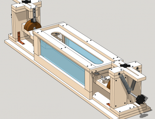
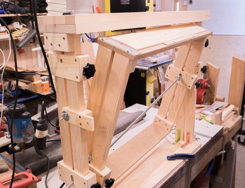
Så hur funkar den då? Ja, det är faktiskt en ganska enkel lösning. Kullagret har ett fast avstånd från bordet med träämnet(hals alt. greppbräda) och profilen som ligger på bordet trycks upp mot kullagret med hjälp av fjädrar som sitter fast i ram och bordsbas (Se bild 2).
Och för att byta en profil är det bara att skruva av muttern som håller fast mallen och ersätta den.
De här profilmallarna är uppblåsta/förstorade med cirka 200%. Anledningen med att förstora profilmallarna är bland annat för att skapa marginal mellan frässtålet. Det är därför viktigt att båda profilmallarna måste vara identiskt uppförstorade. Sen om det är 200%, 300% eller 346,8% spelar ingen roll. Bara att båda är skalade med samma värde (Se bild 3).
Som första test hittade jag en kasserad hals av valnöt som jag kunde prova på. Felet med halsen var bara att avstånden för stämskruv-hålen blev lite ojämna. Vilket inte spelade någon roll i det här sammanhanget. Jag använde en 5-millimeters masonit-skiva som greppbräda och markerade ut fräsavståndet från första bandet och femtonde bandet. Halsprofilsmallarna som jag hade gjort var för progressiv, asymmetrisk hals (+3mm/-3mm). Det enda “felet” som jag lyckades med var att jag hade mallen blev felvänd vid halsfästet – så halsen blev asymmetrisk och inte progressiv asymmetrisk. Resultat blev lyckat ändå och teorin funkade i praktiken!
Strax innan jag skulle provfräsa första halsen fick jag syn på ett led-lysrör som hängde vid arbetsbordet. Och ett sista-minuten-infall blev att jag slängde in det under fräsbordet. Något som jag inte tänkte på innan var att de visuella möjligheterna brukar ju alltid vara marginella när man fräser. Och detta hjälpte verkligen för att synliggöra resultat så eventuellt missade delar kunde upptäckas direkt under arbetets gång och inte efter.
[KGVID]http://www.kappi.com/blog/wp-content/uploads/Neck-Shape-Rig-video-2.mp4[/KGVID]




Very nice implementation of the Scheltema neck profiling jig, Michael! You have added some really useful features – I do like the LED lights to clearly see how the work is progressing. Well done!
Best wishes,
-Johann
Thanks! 🙂
Another thing… You can also use it to do compound fingerboards! 🙂
Yes, you are absolutely correct 🙂 This is such a useful jig – just change the pucks. I’m looking forward to see a fingerboard done on your jig! Again, very well done 🙂
-Johann
Hejsan kollade in din fräsvagga verkar kanon, håller nu på att bygga en. När jag kollar ser jag att att göra profiler kommer fungera perfekt, förstår dock inte hur kan lägga en radie på en greppbräda då ämnet mer eller mindre kommer rotera runt central axeln, du har ingen video hur du sätter upp den för göra en radie på en greppbrädamvh Lennart
Hej! Ursäkta sent svar! Har varit borta o urkopplad från nätet 🙂
Har gjort ett försök med att göra greppbrädor genom att ändra profilen men det fungerar inte så bra. Det blir en handexercis som heter duga och man får verkligen ha starka nypor om man skall få till det (fjädrarna blir väldigt spända när man skall fräsa kanterna). Jag gav upp den idén helt enkelt. Kör min tidigare fräsvagga för greppbrädor som du kan hitta här; http://www.kappi.com/blog/2015/10/diy-plan-for-a-fingerboard-radius-jig/ . Har sett andra vaggor där man byter axel-fästen på sidorna. Får se om jag kan få till det i nästa version 😉
Hi, this is a great jig, are you going to make any plans available??
Thanks! 🙂 Yes, I will. Soon 😉
Hello Michael
Your website is so inspiring for beginner in guitar building like me. Thank you so much lots of useful info here. Making neck profile by hand is big challange for me. This jig is pure gold. I’m traying to recreate this jig in Sketch up. Is the overall length crucial or can there be any deviations? I’m most interested in the relations and length of pucks (if it is the correct term) It would be great if you put your plans on this jig.
https://imgur.com/a/CeSnzd1
Hi Mare! And thanks! 🙂
The length on the moving plane doesn’t matter as long it’s straight. There are going to be some tensions with the springs so my recommendation is to not use any soft wood material.
Regarding the “pucks”. I assume that it’s the “neck profile blocks” you’re referring to. (That’s what I call it. Naming is tricky and will be invented along with new jigs). Yes, the length & height on those is important that they’re enlarged with the same percent. I think I used 200% on the printout templates.But you can use less. It depends on the distance between the router bit and the neck. The larger neck profile blocks, the more distance, longer router bits. You need distance to be able to turn the plane 90 degrees, so don’t make the neck profile blocks to small (e.g. 120%). Then you will probably not be able to to turn the plane more than 10 degrees, something.
Hope this make sense 😉
BR
Michael
Hi Mare!
Here’s the plan for the Neck Router Jig that you asked for.
Happy new year & cheers!
Michael, this is a great jig! One question: how to calculate the right value for how much to scale up the model profiles? What is the mathematical formula? And if I understand correctly, by having the different respective ratios for the model profiles (corresponding to the wanted neck profile at the nut end and body joint end) one gets a progressively changing profile and the only job left is just to finish the surface… no more shaping work needed?
Thanks Pertti!
My thoughts was also that I would need a formula for this. But it was actually simpler then I thought. I used 200% of the original size. The importance is that both profiles have the same scale-up values. You can use bigger but than you have larger turning movements and you need longer shafts on the router bits to go down to its original size.
So to simplify things… I used Adobe Illustrator to draw the exact profile sizes and printed out 200% larger sheets for the templates. This way you can do ANY type of profiles; D, C, V, asymmetric, progressive asymmetric shapes. Even copy an old guitar profile.
And yes, what’s left is some finish activities if you don’t want to tweak some more 🙂
BR
/Michael
Thank you, Michael. Have you changed the method for radiating fretboards to the same process? Or are you still using the taller jig? Ian
sorry, radiusing, not radiating!!! LOL
Hi Ian! No I’m still using the old trustworthy Fingerboard Radius Jig (the taller jig) for the fingerboard work 😉 I just published a video on how that jig works… Check it out: http://www.kappi.com/blog/2018/04/fingerboard-radius-jig-in-action/
Thank you for the fingerboard radiusing video. I will build one this weekend.
When you created the neck profile model profiles, did you need to extend (project) the lines beyond the ends of the fretboard to determine the appropriate sizes and cut a slightly small profile on the nut end and a slightly larger profile on the bridge end to achieve the right profile at the actual neck locations? Or am I overthinking it? I would love to see plans for it . . . really cool!
Hi Ian!
Do you mean the templates for the neck profile jig? No, your not overthinking! 🙂
There are two different templates for the neck; The thinner profile at the head end and the thicker profile at the body end. I resized them to 200% because you need to count in a distance between the router bit and the wood. The purpose is also so you can actually follow the profile and any size above 200% will work. The bigger profile… the smaller and more accurate movements.
I also included the extra height of fingerboard in the profile. But be aware! if you use a thicker fingerboard material (1-2 mm is enough) there are a risk that you gonna hit the truss rod. Did that mistake on one neck. 🙁 But I suppose that’s part of the learning experience.
I can upload my profiles as a pdf-file later this week, so you can use them as a template.
BR
/Michael
Hi Michael,
I’ve shaped a few fingerboards thus far, and I’ve eliminated the blowout issue I had before by changing the direction I’m routing. I’m going to build the neck jig next. Any chance you can upload some of your profiles?
Thanks so much!
Ian
Hi Ian! Here are some measurements and profiles 🙂 …
http://www.kappi.com/blog/2018/06/neck-shape-metrics-templates/
BR
/Michael
One more question . . . If you were to rebuild the fretboard jig, would you construct the top to allow for a plung router instead of the flat Bosch base? Any advantage to taking smaller amounts off the edges initially? Or is the amount taken off with the radius small enough that it is inconsequential? Thanks so much, and I hope to be able to repay you one day.
Hi Ian! I prefer the smaller Bosch GKF 600 for both jigs (so far). It’s easier to handle with one hand.
Using a plung router will work but then you need to use both hands if you don’t have added bearings or something similar on the router board to reduce the friction. And it will be harder to inspect at the same time. The advantage with plung router could be that you can adjust the router bit height without removing it from the router board at the top of the jig.
Reg. taking off the edges, initially…
My experience is that if you begin with smaller steps at each turn, it will reduce the risk of getting “router tracks” that will end-up decreasing the fingerboard height 1 or 2 millimeters.
BR
/Michael
I completed my jig, using your concepts and basic plans. However, I increased the size to allow for a 20” radius, and I made it longer to more easily accommodate a bass fingerboard. It worked great for both a 12” radius board and a 7.25” board for an acoustic bass I have underway – based on the Tinozza bass designed by Motola. I am using a Bosch Colt on a plunger base, for the same reason you suggested. I did have some minor blow-out on the edge of a bocote fingerboard, but I will shave that off and add binding.
I am first and formost a woodworker, and then a luthier. But I really want to automate the items I simply don’t enjoy – like sanding a fingerboard for hours to get the correct radius. Thanks to you, that is now cut to about 15 minutes of finish sanding.
Next will be the neck carving jig – then I will be set. I am really looking forward to the neck jig. Can you please provide some of the templates you use?
Thank you so much!
Ian
[…] two years ago I finished the Neck Router Jig and did a post in Swedish about the idea and how it works. And over the past years, I got some request on a plan for this […]
Hello Michael! I have very much enjoyed building this Jig, and I thank you very much for your contribution to all of us Amateur Luthiers! I have one question, I could not find a dimension on the drawings. What is the dimension from the bottom of the bearings to the top of the adjusting arm? Thank you!
Hi, Daniel!
Thanks! Yes, have missed that! 😉
The height from bottom of the bearing to the top of the adjustment arm is totally 80mm.
My bearing is 22mm in diameter, appr. 3mm space between bearing & adjustment arm.
The height of the adjustment arm is totally 55mm.
BR/
Michael Käppi
Very nice design. I am currently building one myself based on some different plans. I like how you have mounted your templates/cogs to the work surface. Mine are attached by sliding them onto the axis and screwing them into the end of the work suface. Putting the router on a separate and removable rail is genius! Most I have seen require the ends of the jig to be attached to each other by the rails – and this engineering means that it can come out of alignment too easily. Your design solves that problem very well!!